
Privacy policies
GDPR data Terms of use Cookies policy Privacy policy Delivery and Payment How to order?
Privacy policies
GDPR data Terms of use Cookies policy Privacy policy Delivery and Payment How to order?

Code: NoiseKen EPS-3007
Description
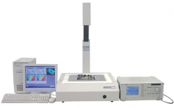
Niear field scanner system to "visualize" the inteference properties of the circuit board
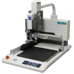
The EMC PRECISION SCAN is a scanner system to measure RF near-field emissions from a printed circuit board under test in normal offices or similar electromagnetic environments by utilizing an X-Y axis antenna probe scanning mechanism. The scanning results are represented on the user's PC monitor as frequency spectrum charts and field intensity distribution color maps, the latter of which is superimposed on the actual board image captured by the CCD camera mounted on the scanner main unit, allowing the user to easily locate the exact sources of emission.
FEATURES
APPLICATIONS
This product is now used in the following applications. Our company is continuously developing various new applications in cooperation with our customers. For example:
SPECIFICATIONS
Main unit/Controller
|
Scanning method |
Scanning of micro-electromagnetic field probe by XY stage |
|
Analysis of detection signal |
Analysis using spectrum analyzer |
|
Frequency response |
30MHz ~ 1.5GHz (standard) |
|
Low Frequency response (option) |
150kHz ~ 100MHz |
|
Control method |
Control by personal computer |
|
Scanning area |
300 (length) x 350mm (Width) maximum |
|
Scanning resolution |
1.0mm x 1.0 mm (depending on an antenna probe) |
|
Minimum scanning step |
1mm/0.1mm step |
|
Power supply |
AC95~120, 210~250V 50/60Hz, 150VA |
|
Dimensions and weight |
(W) 601 x (H) 980 x (D) 662mm |
|
Weight |
Approx. 37kgs |
|
Scanning probes |
Probe A (for vertical magnetic field) , Probe B (for horizontal magnetic field), Probe C (for electric field) |
|
Function |
Scanning frequency range setting, Comparison, Filing and printing the measured data, Emission spectrum display, Search of source of maximum noise emission, Display of the emission intensities from the PCB under test, Synthesization of the emission data and overlaid on real-time image of the PCB |
Personal Computer (Required specifications)
|
Compatible machine |
IBM PC-AT compatible machine running the Windows® XP |
|
OS |
Microsoft® Windows®XP, WindowsVista®, Windows7® |
|
Software |
DirectX® version 2.0 after is necessary. (Direct® version 5.0 is recommended.) |
|
Expansion Slots |
2 x full height PCI slots (for the Pulse Motor Board and the Video Board) |
|
Expansion Board |
GP-IB Board (Using IRQ) |
Measurement function
|
System of unit |
Level: dBµV/dBm, Frequency: MHz (Linear scale) |
|
Compatible spectrum analyzer |
Agilent Technologies: E4402B Please consult with our company about other supported analyzers. |
More products NOISEKEN
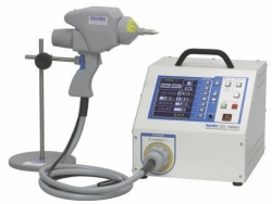
IMPULSE NOISE SIMULATOR EMC TESTING NOISEKEN INS-4020/ 4040
• INS-4020 (2kV) : 0.01 ~ 2.00KV ±10% with 50 ohm load, 10V step |
PCB BOARDS RADIATION EMISSIONS MEASUREMENT SYSTEM NOISEKEN EPS-6000
• Measurable up to 8GHz in the frequency range |
HIGH VOLTAGE LIGHTING SURGE SIMULATOR NOISEKEN LSS-F02
• "Output voltage 15kV, current 7500A" which can conduct breakdown resistibility test |
ESD ELECTROSTATIC DISCHARGE SIMULATOR NOISEKEN ESS-B3011/ESS-L1611
• ESS-B3011 : 0.2 to 30.0kV |
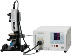
ESD ELECTROSTATIC DISCHARGE SIMULATOR FOR SEMICONDUCTOR CIRCUITS NOISEKEN ESS-6002/ 6008
• ESS-6002 Output voltage: 10V ~2.0kV ±10% (1V step) |
|
FAST TRANSIENT BURST SIMULATOR NOISEKEN FNS-AX3
• 4.8kV maximum peak voltage |
ESD ELECTROSTATIC DISCHARGE SIMULATOR NOISEKEN ESS-2000AX
• 0.20kV~30.0kV Output voltage range |
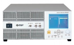
PULSE 2B, 4 GENERATOR AUTOMOTIVE TRANSIENT SURGE SIMULATOR NOISEKEN BP4610
• Pulse 2b and Pulse 4 generating unit |
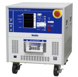
LIGHTING SURGE SIMULATOR NOISEKEN LSS-6230
• Lightning Surge Simulator conforming to IEC61000-4-5 ed2 Standard |
RF EMISSION RADIATION PRECISION SCANNER NOISEKEN EPS-3007
• Provides an amplitude versus frequency plot for each antenna probe position and field intensity distribution map by a single scan |


