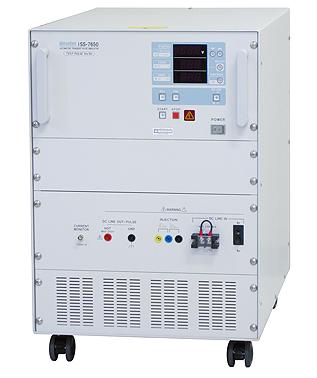
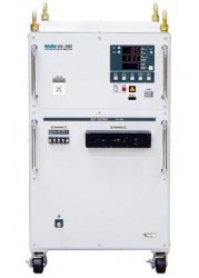
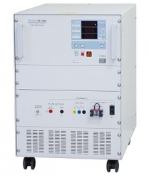
Pulse 5a, 5b Generator Automotive Transient Surge Simulator NoiseKen ISS-7650

Code: NoiseKen ISS-7650


Description

  • Pulse 5a and Pulse 5b generating unit
  • A built-in 60V/30A Coupling Network allows independent operation.
  • Capacitive - resistive (inductive) discharge circuitry in strict conformity with the standard and with the actual car environment.
  • Equipped with a programmable clip circuit that can produce Pulse 5b clipped waveform in steps of 0.1V without externally attaching a zener diode.
  • Pulse 5b clipped waveform is pre-eminent in smoothness.
  • Serial or parallel pulse coupling selectable.
  • Pulse repetitions controller provided (30s to 999s and 1 to 999 pulses)


SPECIFICATION


Parameters

Specifications

Counter

1~ 999 Count,  7 Segment LED

Cycle Timer

30s ~ 999s , 1s step   7 Segment LED

Interlock

Control by External Input, Contact Point or Open Collector
L Level: 0V ~ 0.4V ,        H Level: 2V ~ 4V

Warning Lamp

Option Model: 11-00008A

Current Monitor

Output Unit

10mV/A

Characteristic Freq

DC ~ 150kHz,  Approx. -3dB

Error Tolerance

±5% (DC Measure Value) ±0.8Amax (Offset) at 25°C

Withstanding Voltage

DC60V (BNC Terminal Exterior: FG)

Form

BNC Terminal
(Oscilloscope Wave Verification 1M ohm Input)

Circuit Breaker

Rated Current 40A

Remote Control From PC

Interface

Option: Optical Interface Unit Model: 07-00022A

Software

Option: Remote Control Software Model: ISS-7601

Compatible OS

Windows XP

DUT capacity

DC60Vmax, 30Amax

Power supply

AC100V, 110V, 120V, 200V, 220V, 240V ±10% (50/60Hz)

Operating temperature and humidity

 23°C±5°C / 25~75% (No dewing shall occur.)

Dimensions

(W) 430 X (H) 670  X (D) 660 mm (Projections excluded)

Weight

Approx. 100kgs

Power consumption

Charging: Approx. 600VA,     Standby: Approx. 150VA

Standard accessories

Instruction manual
Spare fuse 6.3A
Interlock plug
DC injection selection plug
Current monitor coaxial cable
DC input cable 2m
Output cable 2m
Short lead cable (for waveform verification)


Pulse 5a

12V system

24V system

Output Voltage (Us)

20V ~  100V±10% (0.5V step)

20 ~  200V±10% ( 0.5V step)

Output Resistance (Ri)

0.5 ohm ~   8 ohm (0.5 ohm step)

 1 ohm ~   8 ohm (0.5 ohm step)

Duration (td)

40ms, 100ms, 200ms, 350ms,
400ms ±20%

100ms, 200ms, 350ms, 400ms
±20%

Rise time (tr)

10ms-5ms/ +0ms

10ms-5ms/+0ms


Pulse 5b

12V system

24V system

Output Voltage (Uss)

10V ~   40V ±10%  (0.1V step)

Open Voltage (Us)

100V>=Us>Uss

200V>=Us>Uss

Duration (td)

Varies dependent on Pulse 5a (1ms step)


More products NOISEKEN
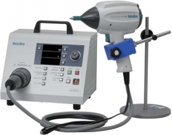
ESD ELECTROSTATIC DISCHARGE SIMULATOR FOR SEMICONDUCTOR CIRCUITS NOISEKEN ESS-6002/ 6008

• ESS-6002 Output voltage: 10V ~2.0kV ±10% (1V step)
• ESS-6008 Output voltage: 100V ~ 8.0 kV±10% (10V step)
• A simple probe stand and test fixture plus a pair of miniature test leads
• Narrow pitch DUT can be tested in semi-automatic manner
• Each probe has a coaxial interface with an external measuring instrument.


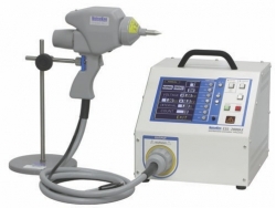
ESD ELECTROSTATIC DISCHARGE SIMULATOR NOISEKEN ESS-2000AX

• 0.20kV~30.0kV Output voltage range
• Fully programmable menu-driven simulator providing three operation modes: IEC standard, Manual and Sequence
• 5.7-inch color LCD for easy setting and good visibility
• Unique shape for the operator's easy access to the controls and displays even when the unit is put on the floor level (ground plane)
• Communications with PC through the optic serial interface
• wide variety of the dedicated options


IMPULSE NOISE SIMULATOR EMC TESTING NOISEKEN INS-AX2

• INS-AX2-220/250 : 0.01 ~ 2.00kV±10% at 0.01kV step Pulse output voltage
• INS-AX2-420/450 : 0.01 ~ 4.00kV±10% at 0.01kV step Pulse output voltage
• Floating output
• 8 pulse widths installed: 10ns, 50ns, 100ns, 200ns, 400ns, 500ns, 800ns and 1000ns
• Internal switchable terminators
• Easily changeable and safety-interlocked outlet panel (EUT interface)
• 3 channels EUT fail input


ESD ELECTROSTATIC DISCHARGE SIMULATOR NOISEKEN ESS-S3011

• 0.2 to 30.0kV +/-5% (30.5kV Maximum)
• 0.2 to 10kV: 0.05V step, 10.0 to 30.0kV: 0.1kV step
• EN/IEC 61000-4-2 Ed2 Compliant
• ISO 10605 Ed2 Compliant
• Pre-test
• Ten-key & Rotary knob to ease the setting
• Infra-red Remote Controller to allow remote Generator setting


PULSE 2B, 4 GENERATOR AUTOMOTIVE TRANSIENT SURGE SIMULATOR NOISEKEN BP4610

• Pulse 2b and Pulse 4 generating unit
• +-60V 10A DC - 150kHz built-In bipolar amplifier
• Functions as the DUT power supply for testing with the other pulses
• Upgradeable to 15A or 30A by use of an optional external power supply


SOURCE-VOLTAGE DIP AND SWELL SIMULATOR NOISEKEN VDS-1007/ 2007

• VDS-1007 : 1kVA Power
• VDS-2007 : 2kVA Power
• Enable to enrich EMC preliminary tests with the remote control as an AC stabilizing power source
• Enable IEC61000-4-11/13/14/28 precompliant tests
• Usable to be power source for IEC61000-3-2-2 precompliant measurement


VOLTAGE DIP AND SWELL WAVEFORMS SIMULATOR NOISEKEN VDS-2002

• Conforming to IEC 61000-4-11
• Fully compliant with all the test generator requirements of IEC standard.
• One unit solution for dip, swell, interruption and variation tests up to 16A 290V single phase AC
• Interruption test up to 16A 125V DC (*)
• Two motor-driven transformers approach enables switching between any voltages (*)
• Preset IEC test levels 0%/40%/70%/80% plus additional 120%


FAST TRANSIENT BURST SIMULATOR NOISEKEN FNS-AX3

• 4.8kV maximum peak voltage
• 2MHz pulse repetition rate
• Conforming to IEC/EN 61000-4-4 (Second Edition-2004)
• Reverse polarity per burst
• Automatic ramp operation
• Manual, IEC level and sequence modes


PULSE 1, 2A GENERATOR AUTOMOTIVE TRANSIENT SURGE SIMULATOR NOISEKEN ISS-7610

• Pulse 1 and Pulse 2a generating unit
• A built-in 60V/30A Coupling Network allows independent operation.
• Wide variety of selections of the output resistances Ri and Pulse Widths td and their combinations


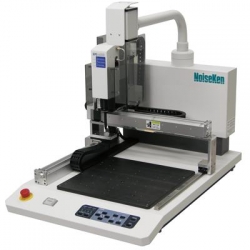
RF EMISSION RADIATION PRECISION SCANNER NOISEKEN EPS-3007

• Provides an amplitude versus frequency plot for each antenna probe position and field intensity distribution map by a single scan
• Electric and magnetic fields are separately detected
• 3D graphical representation and zoom capability for a given area
• Comparison before and after a modification or improvement
• Scanning by a single antenna probe to minimize error between each measurement point
• 3GHz maximum frequency response (option)
• Standard included three kinds of antenna probes (Probe A, Probe B and Probe C)