
Privacy policies
GDPR data Terms of use Cookies policy Privacy policy Delivery and Payment How to order?
Privacy policies
GDPR data Terms of use Cookies policy Privacy policy Delivery and Payment How to order?

Code: Tekbox Open Tem Cells
Description
Radiated emission tests are typically carried out in anechoic chambers, using antennas to pick up the radiated signals. Due to bandwidth limitations, several antennas are required to cover the complete frequency range. Furthermore, it requires much space and the cost of the equipment for a standard conformant setup is immense.
An engineer of a small or medium size enterprise usually has to rely on his experience and on best practice methods in order to design an EMC compliant product. Nevertheless, it is estimated that > 50% of products fail testing first time around. Anytime an engineer sends a new product for compliance testing, it is a shot in the dark. Failing is very expensive. Not only that re-testing costs are high, but also the project schedule and market introduction gets delayed.
What is needed is an affordable laboratory set up to measure radiated emissions in the own lab, prior to compliance testing. A TEM cell is the right piece of equipment for desktop testing of radiated emissions. Tekbox developed open TEM cells to cover the complete frequency range up to 2GHz and with usability even at frequencies beyond.
Combined with a spectrum analyzer, products can be tested before and after EMC related design modifications. A set up with a TEM cell will not deliver exactly the same quantitative results as a measurement in a certified test house, however it will give an excellent indication on whether the design suffers from excessive radiated noise or not. The engineer will clearly see, whether his changes improved or deteriorated the EMC performance or whether it remained unchanged. Using TEM cells eliminates the guesswork.
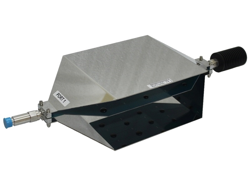
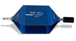
A TEM cell is a stripline device for radiated emissions and immunity testing of electronic devices. It is not a replacement, but due to its size and cost it is a convenient alternative to measurements in an anechoic chamber.
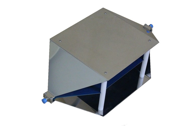
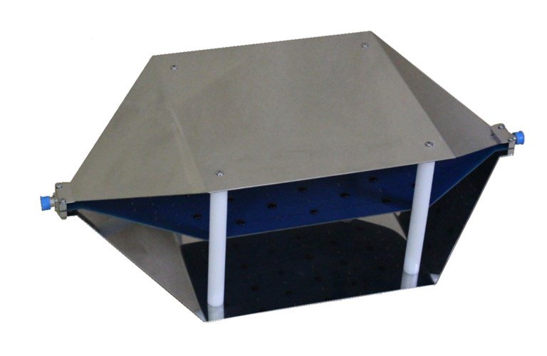
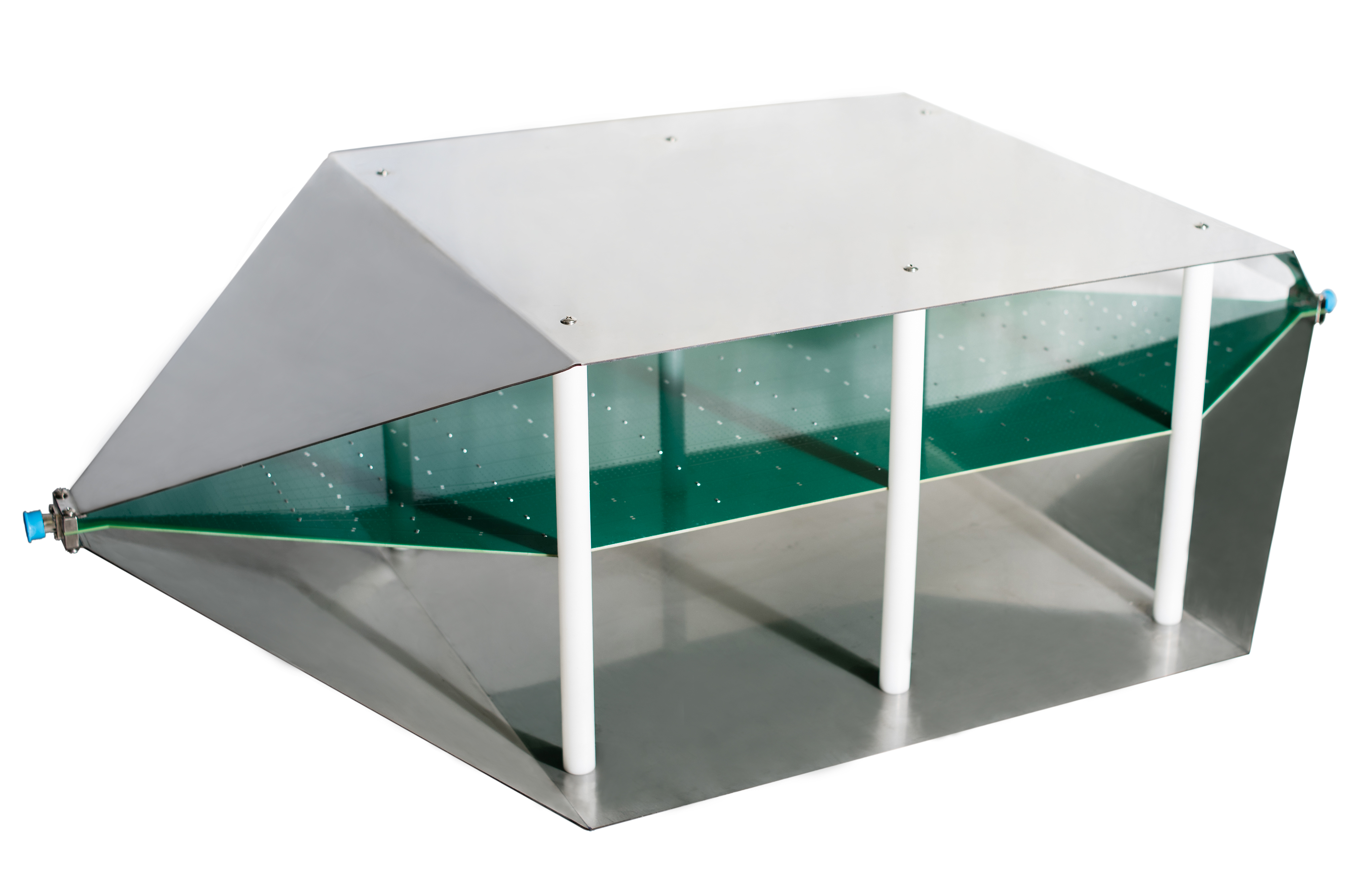
A TEM cell consists of a septum, the conductive strip in the centre section and walls which are connected to ground. The geometry is designed to present a 50O stripline. The device under test (DUT) is placed in between the bottom wall and the septum.
The TBTC1/2/3 are so called ½open TEM cells½, which got no side walls for convenient placement of the DUT. It may pick up RF background noise, which however can be taken into account by doing a measurement of the cell output signal before powering on the DUT.
Tekbox open TEM cells got a better frequency response compared to standard TEM cells of similar size. TEM cells suffer from higher order wave modes which limit the usable bandwidth. A unique design feature of the Tekbox TEM cells implements resistance perpendicular to the desired propagation direction of the wave. Consequently higher order wave modes and resonances are suppressed.
All TEM cells are supplied together with a 50O/25W RF termination, a DC block to protect the spectrum analyzer or RF receiver input and a N-Male to N-Male coaxial cable.
SPECIFICATIONS:
TBTC0 TEM cell dimensions:
Length: 390 mm
Width: 100 mm
Height: 62 mm
Septum height: 28 mm
Rectangular area under the septum: 19 cm x 7 cm x 2,8 cm
TEM cell connectors: N-female
Nominal cell impedance: 50 Ohm
Wave impedance: 377 Ohm
Maximum RF input power: 10W (limited by supplied 50 Termination)
Input return loss: S11 up to 3.15 GHz < -15dB
Transmission loss: up to 3 GHz < 3dB, up to 6 GHz < 4dB
TBTC1 TEM cell dimensions:
Length: 390 mm
Width: 200 mm
Height: 108 mm
Septum height: 50 mm
Rectangular area under the septum: 19 cm x 13 cm x 5 cm
TEM cell connectors: N-female
Nominal cell impedance: 50 Ohm
Wave impedance: 377 Ohm
Maximum RF input power: 25W (limited by supplied 50 Termination)
Input return loss: S11 up to 1.2 GHz < -20dB, up to 2.1 GHz < -17dB, up to 3GHz < -14dB
Transmission loss: up to 1.4 GHz < 1 dB, up to 2.1 GHz < 3dB, up to 3 GHz < 6dB
TBTC2 TEM cell dimensions:
Length: 636 mm
Width: 300 mm
Height: 205 mm
Septum height: 100 mm
Rectangular area under the septum: 23 cm x 28 cm x 10 cm
TEM cell connectors: N-female
Nominal cell impedance: 50 Ohm
Wave impedance: 377 Ohm
Maximum RF input power: 25W (limited by supplied 50 Termination)
Input return loss: S11 up to 800 MHz < -15dB, up to 1.5 GHz < -10dB, up to 3GHz < -14dB
Transmission loss: up to 800 MHz < 1 dB, up to 1.15 GHz < 3dB
TBTC3 TEM cell dimensions:
Length: 1038 mm
Width: 501 mm
Height: 305 mm
Septum height: 150 mm
Rectangular area under the septum: 36 cm x 48 cm x 15 cm
TEM cell connectors: N-female
Nominal cell impedance: 50 Ohm
Wave impedance: 377 Ohm
Maximum RF input power: 25W (limited by supplied 50 Termination)
Input return loss: S11 up to 700 MHz < -16dB
Transmission loss: up to 730 MHz < 3 dB
DC-Block 50V-6GHz-N
Connectors: N-Male/Female
Nominal impedance: 50 Ohm
Max. continuous RF power: 2W
Max. continuous RF voltage: 50V RMS
Frequency: 500kHz to 6 GHz
VSWR: = 1.2
RF-Termination 50O-3GHz-25W-N
Connector: N-Male
Nominal impedance: 50 Ohm
Max. continuous RF power: 25W
Frequency: DC to 3 GHz
VSWR: = 1.2
Third order intermodulation: = 120 dBc
More products TEKBOX
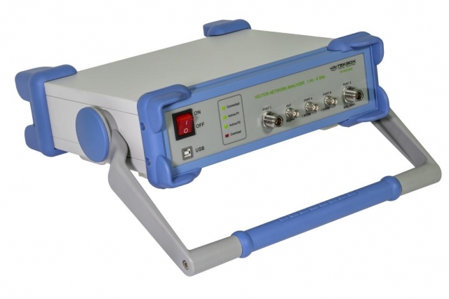
TEKBOX TBVNA-6000 6GHZ VECTOR NETWORK ANALYZER
• EMI Analyzer 1 Hz "" 110 MHz (Measurement Receiver)
|
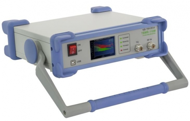
TEKBOX TBMR-110M EMI-ANALYZER 1 HZ-110 MHZ
• EMI Analyzer 1 Hz "" 110 MHz (Measurement Receiver)
|
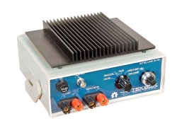
TEKBOX TBOH02 SELF POWERED ACTIVE LOAD
• Operating voltage range: 2V ½ 70V
|
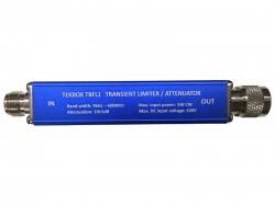
TEKBOX TBFL1 TRANSIENT LIMITER
• Frequency range: 9 kHz ½ 600 MHz
|
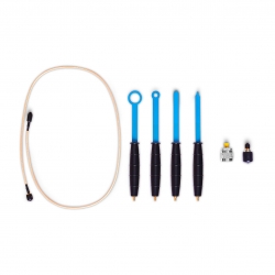
TEKBOX TBPS01 EMC NEAR-FIELD PROBES + TBWA2 WIDEBAND AMPLIFIER
• Slim design for good access in between tightly spaced components
|
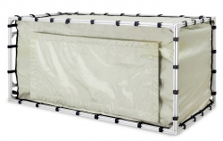
TEKBOX TBST 120/60/60/2 SHIELDED TENT
• Outer dimensions: 120 cm x 60 cm x 60 cm
|
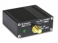
TEKBOX TBWA2/20DB, TBWA2/40DB RF AMPLIFIERS
• EMC probe amplifier
|
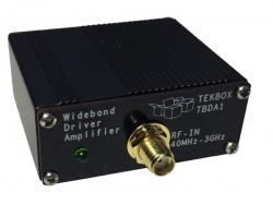
TEKBOX TBDA1/14DB, TBDA1/28DB RF AMPLIFIER
• RF driver amplifier
|
TEKBOX OPEN TEM CELLS FOR EMC PRE-COMPLIANCE TESTING
• All TEM cells are supplied together with a 50O/25W RF termination, a DC block to protect the spectrum analyzer or RF receiver input and a N-Male to N-Male coaxial cable. |
TEKBOX TBLM1 LISN MATE
• Frequency range: 30 kHz ½ 110 MHz
|


