
Politici de confidentialitate
Date GDPR Termeni utilizare Politica cookies Confidentialitate Livrare si plata Cum comanzi?
Politici de confidentialitate
Date GDPR Termeni utilizare Politica cookies Confidentialitate Livrare si plata Cum comanzi?

Cod: NoiseKen EPS-3007
Descriere
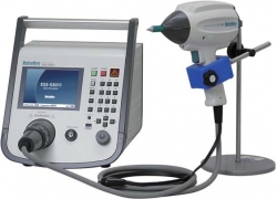
Niear field scanner system to "visualize" the inteference properties of the circuit board
The EMC PRECISION SCAN is a scanner system to measure RF near-field emissions from a printed circuit board under test in normal offices or similar electromagnetic environments by utilizing an X-Y axis antenna probe scanning mechanism. The scanning results are represented on the user's PC monitor as frequency spectrum charts and field intensity distribution color maps, the latter of which is superimposed on the actual board image captured by the CCD camera mounted on the scanner main unit, allowing the user to easily locate the exact sources of emission.
FEATURES
APPLICATIONS
This product is now used in the following applications. Our company is continuously developing various new applications in cooperation with our customers. For example:
SPECIFICATIONS
Main unit/Controller
|
Scanning method |
Scanning of micro-electromagnetic field probe by XY stage |
|
Analysis of detection signal |
Analysis using spectrum analyzer |
|
Frequency response |
30MHz ~ 1.5GHz (standard) |
|
Low Frequency response (option) |
150kHz ~ 100MHz |
|
Control method |
Control by personal computer |
|
Scanning area |
300 (length) x 350mm (Width) maximum |
|
Scanning resolution |
1.0mm x 1.0 mm (depending on an antenna probe) |
|
Minimum scanning step |
1mm/0.1mm step |
|
Power supply |
AC95~120, 210~250V 50/60Hz, 150VA |
|
Dimensions and weight |
(W) 601 x (H) 980 x (D) 662mm |
|
Weight |
Approx. 37kgs |
|
Scanning probes |
Probe A (for vertical magnetic field) , Probe B (for horizontal magnetic field), Probe C (for electric field) |
|
Function |
Scanning frequency range setting, Comparison, Filing and printing the measured data, Emission spectrum display, Search of source of maximum noise emission, Display of the emission intensities from the PCB under test, Synthesization of the emission data and overlaid on real-time image of the PCB |
Personal Computer (Required specifications)
|
Compatible machine |
IBM PC-AT compatible machine running the Windows® XP |
|
OS |
Microsoft® Windows®XP, WindowsVista®, Windows7® |
|
Software |
DirectX® version 2.0 after is necessary. (Direct® version 5.0 is recommended.) |
|
Expansion Slots |
2 x full height PCI slots (for the Pulse Motor Board and the Video Board) |
|
Expansion Board |
GP-IB Board (Using IRQ) |
Measurement function
|
System of unit |
Level: dBµV/dBm, Frequency: MHz (Linear scale) |
|
Compatible spectrum analyzer |
Agilent Technologies: E4402B Please consult with our company about other supported analyzers. |
Alte produse NOISEKEN
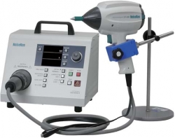
SIMULATOR DESCARCARI ELECTROSTATICE ESD NOISEKEN ESS-B3011/ESS-L1611
• ESS-B3011 : 0.2 to 30.0kV |
|
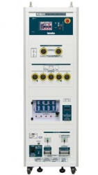
SIMULATOR EVENIMENTE TRANZITORII RAPIDE DECLANSATE NOISEKEN FNS-AX3
• 4.8kV maximum peak voltage |
|
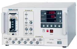
GENERATOR IMPULSURI 1, 2A SIMULARE TRANIZITORII TESTARE EMC AUTOMOTIVE NOISEKEN ISS-7610
• Pulse 1 and Pulse 2a generating unit |
SISTEM MASURA EMISII RADIATII ELECTROMAGNETICE PLACI PCB NOISEKEN EPS-6000
• Measurable up to 8GHz in the frequency range |
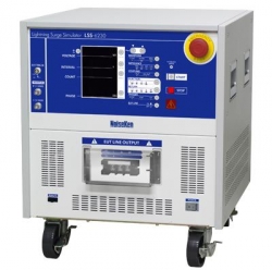
SIMULATOR IMPULSURI INALTA TENSIUNE ECHIPAMENTE DE ILUMINARE NOISEKEN LSS-6230
• Lightning Surge Simulator conforming to IEC61000-4-5 ed2 Standard |
SIMULATOR IMPULSURI ZGOMOT TESTARE EMC NOISEKEN INS-4020/ 4040
• INS-4020 (2kV) : 0.01 ~ 2.00KV ±10% with 50 ohm load, 10V step |
|
GENERATOR IMPULSURI 3A, 3B SIMULARE TRANIZITORII TESTARE EMC AUTOMOTIVE NOISEKEN ISS-7630
• Pulse 3a and Pulse 3b generating unit |
SIMULATOR IMPULSURI INALTA TENSIUNE ECHIPAMENTE ILUMINAT NOISEKEN LSS-F02
• "Output voltage 15kV, current 7500A" which can conduct breakdown resistibility test |
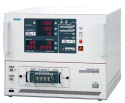
SIMULATOR IMPULSURI ZGOMOT TESTARE EMC NOISEKEN INS-AX2
• INS-AX2-220/250 : 0.01 ~ 2.00kV±10% at 0.01kV step Pulse output voltage |
SIMULATOR DESCARCARI ELECTROSTATICE ESD NOISEKEN ESS-S3011
• 0.2 to 30.0kV +/-5% (30.5kV Maximum) |


