
Privacy policies
GDPR data Terms of use Cookies policy Privacy policy Delivery and Payment How to order?
Privacy policies
GDPR data Terms of use Cookies policy Privacy policy Delivery and Payment How to order?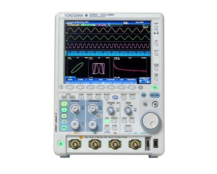

Code: YOKOGAWA - DLM2000 DLM2022 DLM2032 DLM2052 DLM2024 DLM2034 DLM2054
Description
Real time Filter with optimum noise reduction supports a wide range of frequencies (from 8 kHz to 200 MHz)
The DLM2000 series has two types of filters, one processed at the input circuit and one based on MATH functions. These filters are effective for rejecting unwanted signals, allowing observation of only the desired bandwidths.
Real Time Filters
Each channel has 14 low pass filters available from 8 kHz to 200 MHz. The filtered data is stored in internal memory.
Cutoff Frequencies:
200 MHz, 100 MHz, 20 MHz, 10 MHz, 5 MHz,
2 MHz, 1 MHz, 500 kHz, 250 kHz, 125 kHz,
62.5 kHz, 32 kHz, 16 kHz, and 8 kHz
Zoom two locations simultaneously
Combined with the advanced search and cursor/parameter measurement capabilities, the two zoom windows enable users, for example, to see the waveform detail of two parts of the acquisition which can be separated by a long time period.
Two types of waveform searching:
Normally, searching for data takes time and costs money, and long memory is useless without functions for extracting desired data from a large capacity memory. That's why the DLM2000 series does not simply offer long memory, it also provides powerful waveform search functions.
Measure function and statistics
30 waveform parameters from a total of 29 different types can be displayed simultaneously with a high update rate. These include: maximum, minimum, peak-to-peak, pulse width, period, frequency, rise and fall times, and the delay between channels.
The statistics of repetitively measured parameters can also be displayed, such as the mean, maximum, minimum and standard deviation.
Trend and histogram displays
To observe the fluctuations of measured parameters, it is possible to display them as trends. Period-to-period changes can then be easily seen. The variation of parameters can also be displayed as histograms thus providing a statistical visualization.
Measure voltage and time differences automatically
Line or waveform marker cursors can be placed on different displayed waveforms and the absolute values of voltage and time, and their differences, can be simply displayed. A degree cursor can also be used by converting the time axis into a position/degree axis. Six types of cursor are available.
More products YOKOGAWA
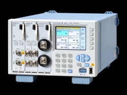

YOKOGAWA AQ2211 FRAME CONTROLLER (3 SLOTS)
• Easy-to-view color display |
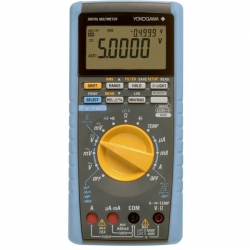
YOKOGAWA DIGITAL MULTIMETER TY720
• True RMS measurement |
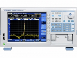
YOKOGAWA - AQ6376 THREE MICRON OPTICAL SPECTRUM ANALYZER
• Long wavelength range: 1500 to 3400 nm |
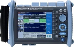
YOKOGAWA AQ1300 SERIES 1G/10G ETHERNET MULTI FIELD TESTER
• Optical and electrical measurement ports for 10M to 1G (AQ1301) and 10M to 10G (AQ1300) are available |
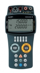
YOKOGAWA MULTIFUNCTION CALIBRATOR CA150 (HANDHELD)
• Vertical Hand-Held Calibrator |
YOKOGAWA CLAMP-ON TESTER CL150 (ACA, ACV, DCV, OHM, 2000A)
• AC/DC voltage and resistance measurements |
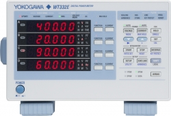
YOKOGAWA - WT300E DIGITAL POWER METER
• Fast display and data update rate: The fast display and a maximum data update rate of 100ms on the WT300E series, offers a short tact time in testing procedures. |
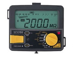
YOKOGAWA DIGITAL INSULATION TESTER MY40
• 3 1/2-digit LCD; |
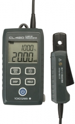
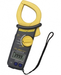
YOKOGAWA CLAMP-ON PROCESS METER CL420 (DC MA CURRENT)
• 0.2% Accuracy, 0.01mA Resolution |
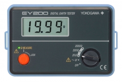
YOKOGAWA EARTH TESTER EY200 (DIGITAL)
• 2P Test leads (for simplified measurement) has a structure that both the safety alligator clip and the test probe are available |


