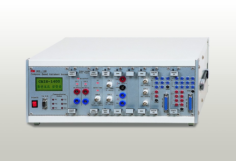
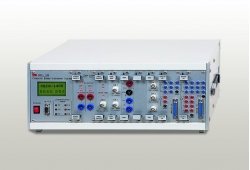
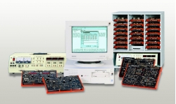
Computer Based Instrument System CBIS-1400

Code: CBIS-1400


Datasheet PDF, 0.56 Mb

Description

MEASURING INSTRUMENT

  • Digital Storage Oscilloscope
    • Channel : 2 channels, 2 x BNC(AC/DC Coupling) + 1
  • External Trigger
    • Sampling Rate : 50MS/s(when using 2 channels)
    • Bandwidth : 25MS/s
    • Resolution : 12bit
    • Accuracy : ±1%
    • Input Impedance : 1M?
    • Overload Protection : ±100V
    • Buffer Size : 128k
    • Interface : USB
  • Variable Power Supply
    • Number of Output Channels : 2 channels
    • Output : Variable Power Supply(0~25V, 1A)x2ea
    • Internal Resistance : < 15m?
    • Stability : < 2.5mV
    • Recovery Time : < 80µs
    • Load Regulation : < 0.05
    • Temperature Coefficient : 0.1%/°C
    • Ripple & Noise : < 5mV
    • Output Current : Max. 1A
      • Range : 100ms to 10s in 3 steps
    • Frequency : 10MHz TCXO
    • Accuracy : 1x10-^(6)(10°C~40°C)
    • Interface : USB
  • Function Generator
    • Number of Output Channels : 2 channels
    • Frequency Range
      • SINE : 1Hz~5MHz, SQUARE : 1Hz~1MHz, TRIANGLE : 1Hz~1MHz
    • Control Method : Variable adjustment on PC
    • Resolution : 0.1Hz
    • Output Voltage : 20Vp-p(10Vp-p into 50?)
    • Attenuator
      • Max. 60dB
      • 2step : 20dB±0.5dB, Variable : 0~20dB
    • DC Offset : ±5V(±2.5V into 50? load)
    • Sweep
      • Mode : Linear
      • Speed : 20ms~5s
      • Range : 1:100
    • Signal Type : SINE, SQUARE, TRIANGLE
    • Interface : USB
  • Multi-Function
    • Analog Input
      • Number of Input Channels : 8 channels
      • Resolution : 12bit
    • Input Range : ±10V
    • Analog Output
      • Number of Output Channels : 2 channels
      • Output Voltage : 0~5V
      • Output Current : 5mA
    • Digital Input
      • Number of Input Channels : 12 channels
      • Input Level : TTL logic level
    • Digital Output
      • Number of Input Channels : 8 channels
      • Output Level : TTL logic level
    • Interface : USB

 GENERAL CHARACTERISTICS

  • Input Voltage : AC220V, 50/60Hz
  • Weight : 12.5kg
  • Dimension : 479(W) x 194(H) x 416(D)mm

 ACCESSORIES

  • Connection Cord : 1set
  • AC Power Cord : 1ea
  • User’s Manual : 1ea
  • Program CD : 1set
 

More products ED

MOTOR / GENERATOR TRAINER UNIT MG-5216

• RIM’s no-load power factor and load power factor
• Load characteristics of separately excited DC shunt-wound generator
• No-load saturation characteristics of generator
• DC shunt-wound generator’s loss and power factor


DC MOTOR/AC GENERATOR MG-5214

• DC motor’s load characteristics
• DC motor’s loss and efficiency
• Alteration of the motor’s rotative directions
• Motor’s speed and torque


HYDRAULICS TRAINER ED-7960

• Convenient parts fixation by ‘one-touch lever’ bases and aluminum profile structure
• Efficient space utilization by mounting parts horizontally/vertically
• 64 hydraulic and electrical/electronic parts plus 20 types of optional components.
• Various hydraulic devices and components for Flexible Manufacturing System


PC BASED POWER ELECTRONICS TRAINER ED-1430

• 5 experimental modules for power electronics covering basic theory and applied experiments
• Capable of real-time measurements on PC by linking it to CBIS-1400 model
• By connecting PC to the Docking station, contact control is implemented on MMI(HMI) based software
• Report on experimental results & electronic manual on PC


EMBEDDED BASED HOME NETWORK TRAINER ED-5967

• Home network control in liaison with Embedded PXA 255/270/272/320
• Power line communication and ZigBee modules with Multi Port in use together
• Embedded


PULSE/DIGITAL COMMUNICATION TRAINER ED-2920

• Modularized by each communicarion type
• PAM, PTM, PCM, DPCM, ADPCM, LDM, ADM, Delta-sigma
• No need to have additional generators (built-in power supply and signal source)
• Can display the test point and measure signals using an oscilloscope


SEQUENCE CONTROL TRAINER ED-4010

• Realistic arrangement of materials used for contact sequence
• Indication of each element’s symbol on the panel


RFID APPLICATION TRAINER ED-3710

• F/W program practices for RFID Reader
• 13.56MHz and 900MHz in common use
• Data Read/Write to 900MHz Tag
• ED-3710 application programming (13.56MHz, 900MHz)
• Fixed Type RFID Reader


EMBEDDED & DSP DESIGN PLATFORM ED-DAVINCI

• One-stop training kit for embedded system, DSP and FPGA
• 7" Wide TFT LCD, 10/100 Ethernet 1Port, Serial 1Port, SD/MMC, ATA and other interfaces


SERVO UNIT TRAINER ED-4270M

• Experiments on various types of special control unit
• Characteristics of Servo Motor and setup of Servo Driver
• Essential components in automation using a PLC position module
• 4mm banana jack to increase wiring capability